
This article explains how to install the optional RS485 Modbus add-on card in a Krypton® Multi. The card enables Modbus communication (for example with a Cloud Connect® Gateway or a PLC/SCADA system) .
Before you begin
- Disconnect the instrument from the power supply and remove all connected sensor, output, and communication cables.
- Work only with the enclosure open and the instrument de-energized.
- Only qualified personnel should install internal option cards.
Installation procedure
- Disconnect the instrument from the power supply and remove all potentially connected cables.
- Open the housing of the Krypton® Multi.
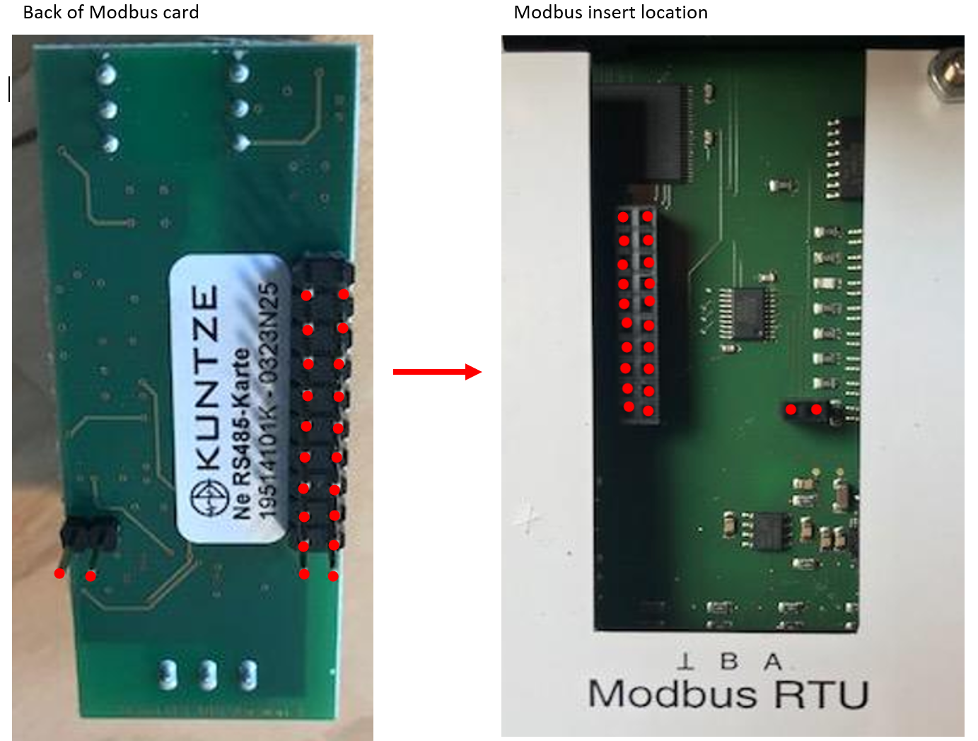
- Remove the RS485 Modbus module from its packaging. Align the pins on the module with the matching connectors on the main board (insert location on the controller PCB).
- The card has 22 prongs on the rear that must mate with the socket on the board. Align the module carefully—offset or bent pins will prevent a working Modbus connection.
- Press the module straight down until it is fully seated. Do not force the card if resistance is uneven; recheck alignment and try again.
- Close the housing and secure the lock pin before restoring external wiring.
After installation
Wire external Modbus or gateway connections only after the card is installed. For Cloud Connect® Gateway wiring (terminals A/B and power), see Gateway Wiring Connections.
Restore power and verify communication from your host system or gateway. If Modbus does not respond, power off, reopen the housing, and confirm the card is fully seated and all 22 prongs engaged correctly.
Important notes
- Do not open the enclosure while the instrument is connected to a power supply.
- Misaligned prongs can damage the board or the module—never rock the card sideways into the socket.
Comments
0 comments
Please sign in to leave a comment.